
When you upload this code to Arduino all the four display starts to count in this fashion: 0000, 1111, 2222, 3333, till 9999 and repeats. To check whether your wiring connections associated with the display and Arduino are correct or not, please upload the below given code to Arduino. This is a strong sign of poor wiring work / incorrectly connected segments. Some are getting partial output from this clock i.e the time is not displaying correctly or some segments are not lighting up or dimly lighting up or the 7 segment displays are acting randomly. In the comments we can see some beginners are not able to successfully build this clock in their first attempt, this is because of the tedious wiring work involved in connecting 7 segment display. Some users reported that by using DS3231 they are just drifting 1 second per month, DS3231 is slightly more expensive than DS1307 RTC and it worth the cost. To get higher accuracy you may switch to DS3231 RTC which has temperature compensated crystal, it has time deviation of just 63 seconds per year or 5.25 seconds per month as per its datasheet. A good quality RTC will have minimal time deviation, but cheaper DS1307 module from china will have more time deviation, this is because there is no temperature compensation for the crystal. We can witness time deviation anywhere between +/- few seconds a month if you are using DS3231 or a couple of minutes per month if you are using DS1307. NOTE: The above code can support DS3231 and DS1307 RTC modules.Īccuracy of Digital Clock with RTC Module:

-// #include "SevSeg.h" SevSeg Display const unsigned long period = 1000 //one second const unsigned long led_period = 500 //LED blink millisecond unsigned long startMillis unsigned long led_startMillis unsigned long currentMillis unsigned long led_currentMillis const int hrs_btn = A0 const int min_btn = A1 const int ledPin = A2 int Hrs = 12 int Min = 0 int Sec = 0 int Time int ledState = LOW void setup () //-(C)-//

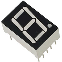
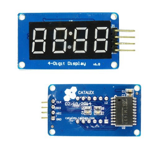
The 4 digits are multiplexed to reduce the number of wires that connects from Arduino to 7 segment displays, this will also reduce the power consumption significantly with the equivalent power consumption of just one 7 segment display we can power 4 or more digits without any noticeable reduction in brightness, this is a huge advantage if you are powering this clock using batteries. The proposed 7 segment clock is a four digit timepiece with couple of LEDs blinking at the rate of 1 Hz between hour and minute digits.
#JAM DIGITAL 7 SEGMENT ARDUINO HOW TO#
How to multiplex 4 Digit-7 Segment Displays:


 0 kommentar(er)
